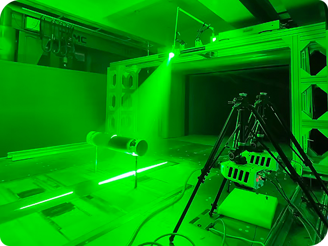
WSRS-braided spaced-structure reinforced sandwich composite is widely used in shock absorbers in aviation, transportation and construction because of its energy absorption, light weight and high delamination resistance.
Due to the complex structure of WSRS interlayer, there is a lack of effective methods to characterize the bearing capacity and failure process of WSRS-WA and WSRS-WE interlayers under mechanical loads.
Researchers from the Textile and Clothing Technology Innovation Center of Hebei University of Science and Technology used acoustic emission (AE) technology to capture the strain energy released by damage under mechanical loading of WSRS of different height specifications (see 3.1 for details), and then used digital image correlation (DIC) technology to observe in real time the failure mode of the damaged area and the synergistic effect images of the surface layer, core pile and foam material, analyze the mechanical properties, AE signal parameters and strain curves, and study and verify the failure mechanism during bending loading.
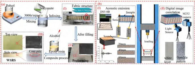
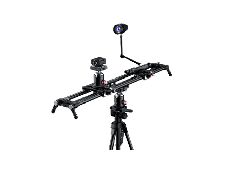
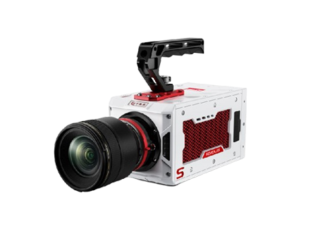
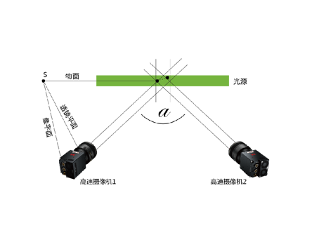
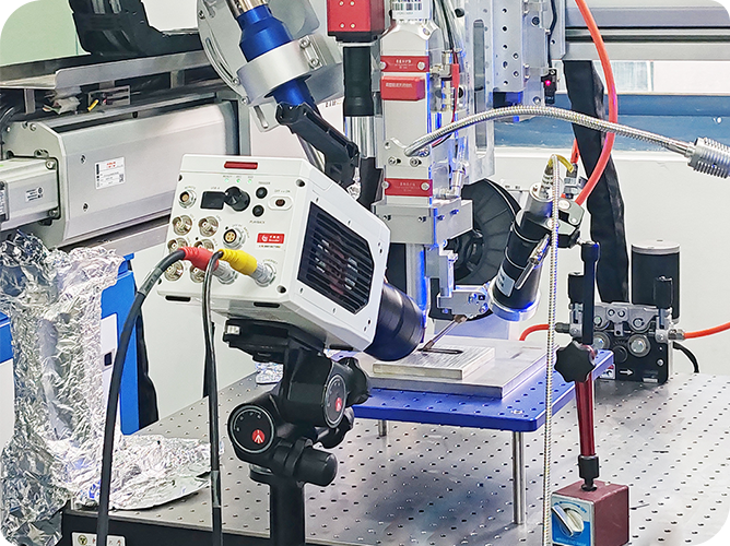
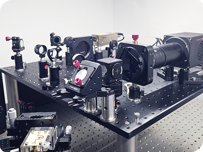
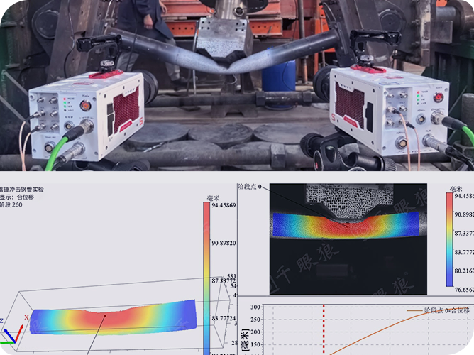
FIG. 1 WSRS material AE equipment DIC equipment
3.1 Prepare six WSRS with different specifications and mechanical properties and use them as standard test specimens.
3.2 Acoustic Emission (AE) detection equipment, with a 40dB amplifier and two RS-2A sensors, captures six AE signals for damage analysis and determines the WSRS failure mechanism.
3.3 Digital image correlation (DIC) strain field measurement equipment is used to capture the full-field strain of the specimen in the WA and WE directions, restore the dynamic damage process of WSRS, and study the bending response mechanism.
3.4 Universal material strength machine, three-point bending test on WSRS, test standard refers to ISO 1209-1-2007(E).
3.5 Scanning electron microscopy was used to analyze the final failure of WSRS and verify the conclusions of AE signal analysis and digital image correlation (DIC) strain analysis.
The middle region of the six WSRS (see Fig. 2) was selected for DIC analysis to obtain the local strain changes between the core and the foam, and the WSRS were monitored in real time using Lagrangian microstrain to compare the trend of the average microstrain of the six WSRS over time (see Fig. 3).
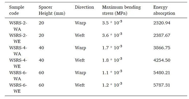
Comparison reveals that WSRS-2 and WSRS-4 have the same strain trajectory, indicating that the compressive strain is greater than the tensile strain, but the microstrain is more abrupt than that of WSRS-4, suggesting that WSRS-2 produces more shear damage. The damage mechanism of WSRS-6 is not obvious, with a stable loading state, the average microstrain varies linearly, and the WSRS-6-WA meridional and WSRS-6-WE latitudinal strain The trend is different, and the average microstrain of WA in the warp direction exhibits the same compressive strain as that of WSRS-4. The latitudinal direction shows obvious tensile strain.
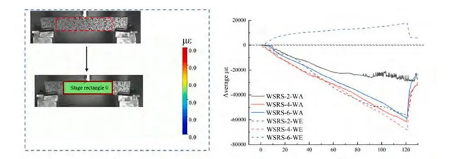
FIG. 2 WSRS strain area FIG. 3 Average microstrain value of WSRS
To further observe the strain trends during the loading of the six WSRSs, strain maps were selected to characterize the failure modes at six different time points, using 20 seconds as the node. The blue region indicates the compressive strain, and the red region indicates the tensile strain caused by the real-time change of microstrain values. Fig. 4 and 5 show that the core layer, as the main failure body, is missing during foam compression.
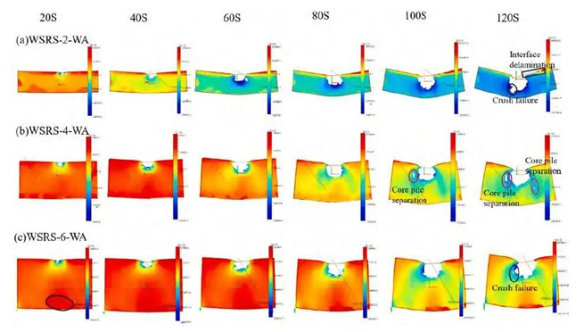
FIG.4 WSRS-WA meridional strain diagram
According to WSRS-WA (Fig. 4), the core layer is mainly affected by tensile strain when compression causes the upper layer to move. As the height increases, the strain graphs show different trends.Within 60 seconds, the core layer of WSRS-2-WA is not strong enough to withstand the stress, causing the compressive strain to shift to the lower layer, which then leads to the compressive strain penetrating through the entire core layer.After 120 seconds, the inner layer of WSRS-2-WA appears to be damaged, and interfacial delamination occurs in the core layer.The compressive strain appears in WSRS-4-WA at 80 seconds, and butterfly-like diffusion.
WSRS-6-WA shows compressive strain only at 100 seconds, indicating that the lower layer is subjected to a weaker tensile effect by the height factor, delaying the compressive strain transfer. Figure 5 shows that WSRS-2-WE and WSRS-4-WE have the same strain trend as WSRS-2-WA and WSRS-4-WA, but all of them are earlier than the latter, with WSRS-2-WE showing compressive strain at 40 seconds and WSRS-4-WE at 80 seconds, indicating that the overall destruction of WSRS-WE is earlier than that of WSRS-WA. 80 seconds later, the upper layer concentrically breaks and the lower layer stretches and appears missing in the strain diagram. Meanwhile, WSRS-6-WE also showed core pile separation (Fig. 5).
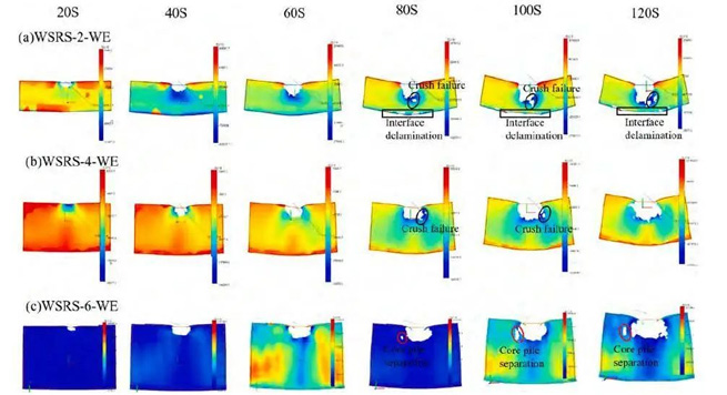
FIG. 5 WSRS-WE zonal strain diagram
Unlike WSRS-2, WSRS-4 and WSRS-6-WA, there is tensile strain on both sides of WSRS-6-WE, which is due to the linkage action of the foam material and the transfer effect of the core pile, increasing the bending strength.
A combination of acoustic emission (AE) techniques and digital image correlation (DIC) methods reveals the dynamic damage processes and bending response of woven spacer structure-reinforced sandwich composites (WSRS).
The results show that the overall compressive strain of WSRS-WE is earlier than that of WSRS-WA and the failure region is more prominent, indicating that the synergistic effect of the core pile structure in WSRS-WE is better than that of WSRS-WA.When subjected to the bending stresses, the load carrying capacity of WSRS is higher than that of the warp direction, which exhibits better integrity and load carrying capacity. The article is extracted from “Combining acoustic emission and digital image correlation analysis fordynamic damage response of woven spacer structure reinforced sandwich composites”.

