1. Experimental Background
The combustion process involves a variety of chemical reactions, and the concentration distribution of the key intermediate product CH 2 O (formaldehyde) can reflect the combustion efficiency. It is of great significance for optimizing the combustion process, improving combustion efficiency and reducing pollution.
Traditional invasive measurement technology will interfere with the combustion flame field, and has a slow response speed and low accuracy. The planar laser induced fluorescence (PLIF) technology has the characteristics of high temporal and spatial resolution, non-contact, and multi-component selection, and can achieve high-precision measurement of CH2O concentration in the combustion flame.
2. Technical Principles
PLIF technology is based on the interaction between laser and matter. When a beam of planar laser of a specific wavelength is irradiated on the target molecules (such as CH₂O) in the combustion flame , these molecules absorb the laser energy and transition from the ground state to the excited state. The molecules in the excited state will spontaneously return to the ground state in a short time and emit fluorescence. The fluorescence signal is collected by a high-speed camera or sCMOS scientific camera, and the CH₂O concentration distribution image in the combustion flame is obtained based on the relationship between the fluorescence intensity and the molecular concentration.
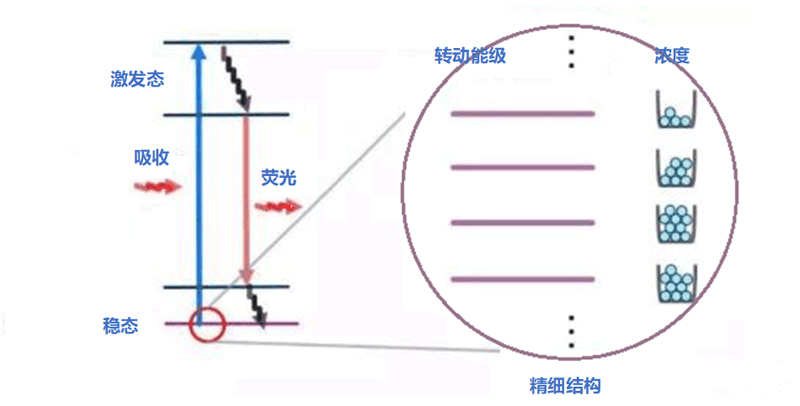
Figure 1 Schematic diagram of PLIF technology
3. Experimental system
The main components of the Thousand Eyes Wolf PLIF experimental system are:
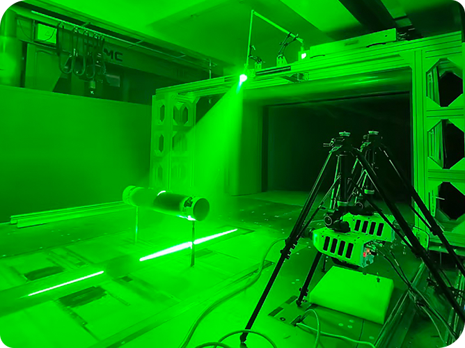
1) The pump laser, with a frequency of 30 Hz and an energy of 180 mJ, is used to generate a planar laser with a wavelength of 355 nm to excite CH2O molecules in the flame.
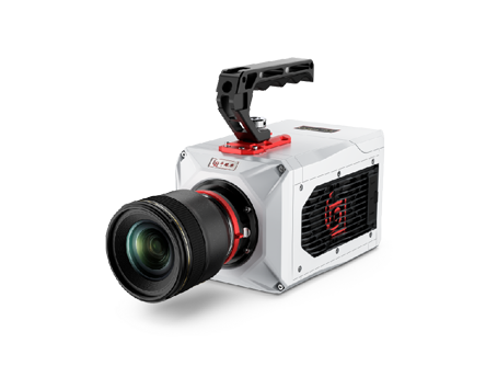
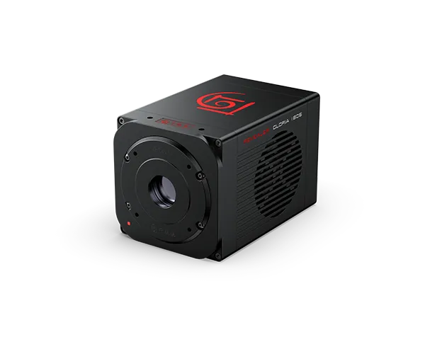
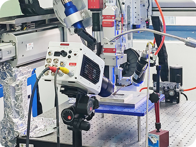
2) Revealer G_Pro series high-speed camera, used to capture flame fluorescence images.
3) P43 phosphor screen image intensifier, used to enhance the fluorescence signal generated by the excited formaldehyde molecules.
4) Revealer synchronization controller, with minimum pulse width of 1ns and time synchronization accuracy of 1ns, is used for precise synchronization of laser pulses, high-speed cameras and image intensifiers.
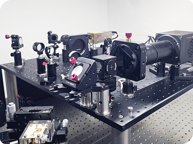
5) Optical components, such as high-reflection mirrors, concave lenses, convex lenses, filters, etc., are used to focus the laser into a thin sheet, collect and filter the fluorescence signal, and improve the signal-to-noise ratio.
6) Flame generator, used to generate a stable combustion flame.
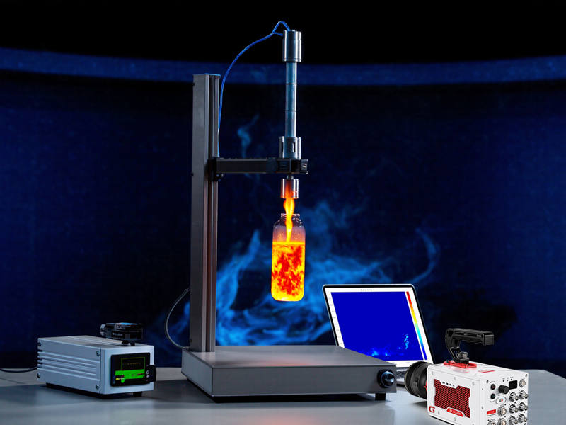
Figure 2 Schematic diagram of the PLIF system
4. Experimental Procedure
The first step is system calibration
The measurement area is filled with 0 mg/m3 , 0.03mg/m3 , 0.05mg/m3 Three concentrations of CH2O were used. Fluorescence images at corresponding concentrations were collected to establish the fluorescence intensity-concentration relationship curve.
Step 2 Data Collection
A high-speed camera with an image intensifier and a bandpass filter was used to capture the fluorescence image of the excited CH 2 O molecules.
Step 3 Data Post-processing
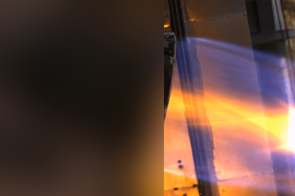
According to the calibrated fluorescence intensity-concentration curve, the grayscale data of the original fluorescence image is converted into pseudo-color data representing the concentration, namely the concentration distribution image. By analyzing the sequence images captured by the high-speed camera, the variation pattern of CH 2 O concentration over time and space is obtained. The pseudo-color image shows that the concentration is higher in the flame front area and lower in the flame tail area.
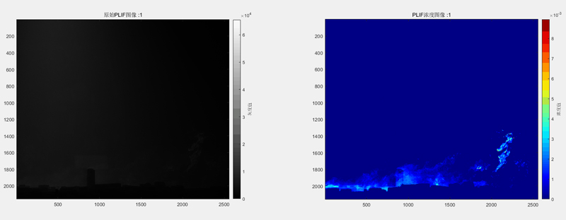
Figure 3 Pseudo-color animation of component concentration
5. Experimental conclusion
As an advanced optical diagnostic technology, the PLIF measurement method can provide high-temporal and spatial resolution images of CH 2 O concentration distribution in combustion flames, helping researchers understand the chemical reaction mechanism during the combustion process and providing experimental data support for improving combustion efficiency and reducing pollutant emissions.
PLIF planar laser induced technology can also be combined with PIV particle image velocimetry technology, and has important applications in turbulence research, chemical engineering, environmental monitoring and other fields.
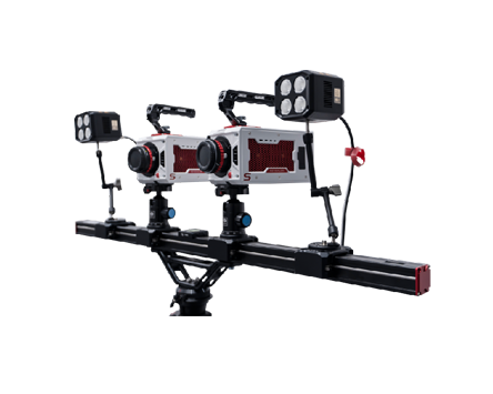
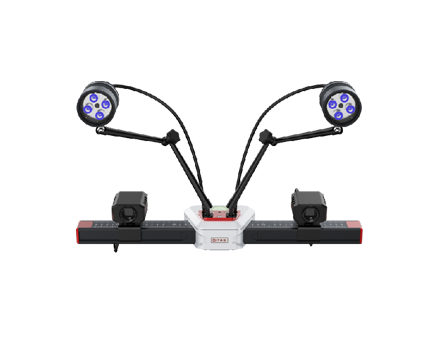
Attached is Revealer's self-developed PIV flow field measurement software and hardware
Self-developed PIV measurement software, suitable for 2D2C, 2D3C, 3D3C, PLIF, PTV, bubble measurement and other application scenarios .
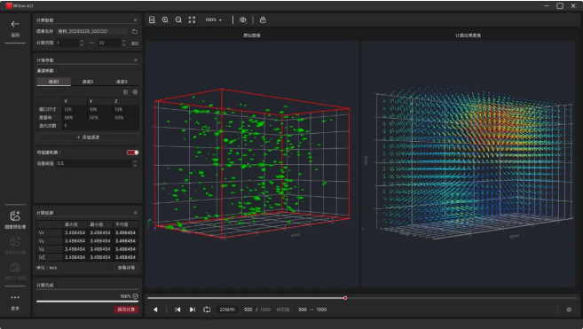
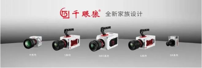
Autonomous and controllable PIV high-speed camera, PIV ultra-clear camera
