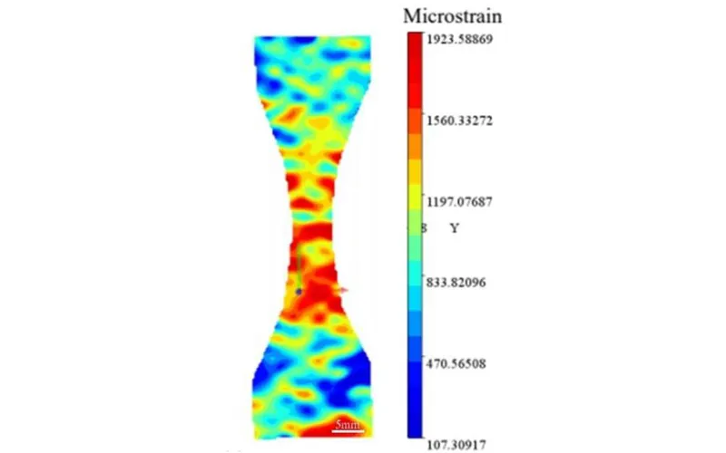
This study adopts the Digital Image Correlation (DIC) system to reveal the fracture behavior and microcracking mechanism of epoxy resin-grouted fractured granite under static and dynamic loading conditions.
The stability control of fractured rock masses is a core challenge in slope reinforcement and tunnel engineering, and grouting reinforcement serves as an essential technical means to improve the mechanical performance of fractured rock masses. The tensile fracture mechanism and microcrack evolution law of fractured rock masses under static and dynamic loads still lack high temporal-resolution observation on the full-field deformation evolution of post-grouting rock masses. Traditional point strain measurement methods are difficult to capture the non-uniform deformation and strain localization characteristics during crack initiation and propagation. The research team of Chengdu University of Technology introduced the Revealer Digital Image Correlation (DIC) technology and acoustic emission (AE) synchronous monitoring system. Static and dynamic Brazilian splitting comparative tests were carried out on epoxy resin-grouted fractured granite with different crack inclination angles, and the toughening mechanism of epoxy resin grouting was analyzed from the perspective of full-field deformation visualization.
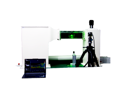
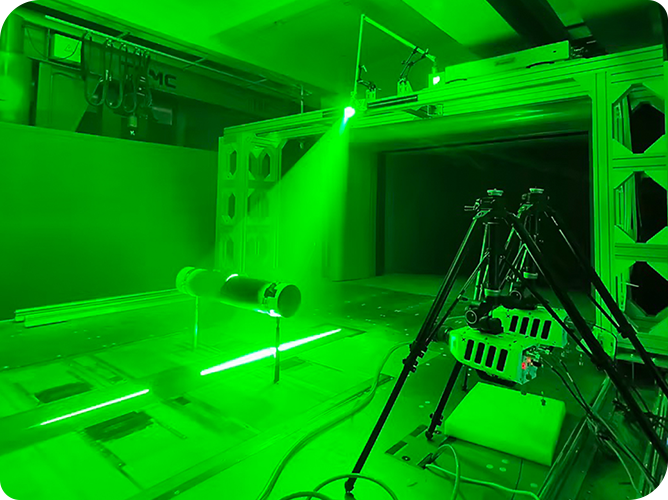
The experimental platform consists of three subsystems: mechanical loading system, Acoustic Emission (AE) monitoring system, and Digital Image Correlation (DIC) measurement system (Fig.1).
Mechanical loading system: A multi-functional rock mechanics testing machine is adopted to perform static displacement-controlled loading and sinusoidal cyclic dynamic loading.
AE monitoring system: With a sampling frequency of 3 MHz and a threshold of 40 dB, it is used to real-time capture elastic wave signals generated during microcrack initiation and propagation.
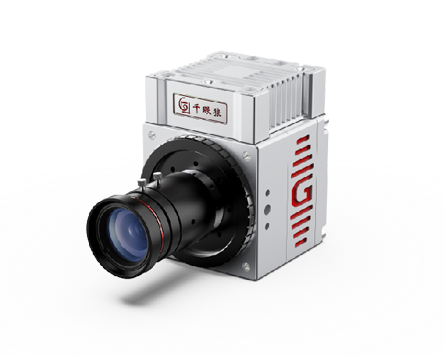
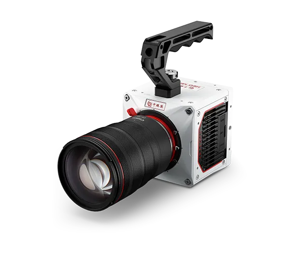
DIC measurement system: The core device is the Revealer GR220 real-time high-speed camera. It supports a maximum frame rate of 2000 fps at a resolution of 1920×1080, and the experimental frame rate was set to 1000 fps. The optical axis of the camera is perpendicular to the specimen surface, with the field of view fully covering the Brazilian disc surface. The image acquisition system achieves time-series synchronization with the mechanical loading system and AE system via a synchronous trigger, ensuring accurate correlation analysis among strain field, load and acoustic emission events.
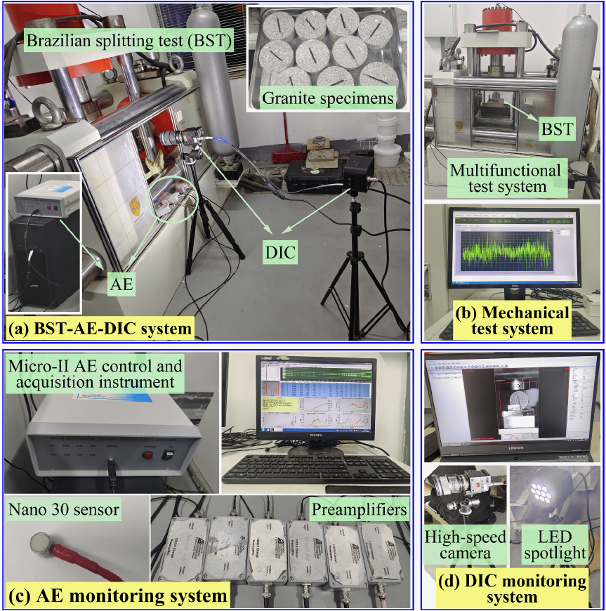
Fig.1 Composition of Brazilian splitting test system, including mechanical loading platform, AE monitoring module, and DIC non-contact optical monitoring system composed of high-speed camera and LED spotlight, realizing synchronous multi-parameter acquisition of rock fracture mechanics, acoustic emission and full-field deformation.
3.1 Specimen Preparation
Two types of granite Brazilian disc specimens were fabricated: Center-Cracked Brazilian Disc (CCBD) specimens with prefabricated central cracks, and Epoxy-resin Grouted Center-Cracked Brazilian Disc (ECBD) specimens.
3.2 Loading Scheme
The inclination angles between prefabricated cracks and the loading direction were set as 0°, 30°, 45°, 60° and 90°. Two testing types were conducted: Static Brazilian Splitting Test (SBST) and Cyclic Dynamic Brazilian Splitting Test (CBST).
In SBST, displacement-controlled loading was applied at a constant rate of 0.001 mm/s until specimen failure. In CBST, static loading was firstly applied to a target load of 30 kN, followed by 1 Hz sinusoidal cyclic loading until fatigue failure. At least three parallel specimens were prepared for each working condition.
3.3 DIC Data Processing
High-speed sequential images were processed by digital image correlation calculation. Subset matching was implemented based on the normalized cross-correlation criterion to obtain full-field horizontal strain, vertical strain and shear strain. The maximum principal strain vector field was further synthesized. The evolution of high-strain zones at different loading stages was dynamically tracked to identify microcrack initiation locations and macroscopic crack propagation paths.
4.1 Verification of Macroscopic Fracture Morphology via DIC
The macroscopic crack contour, initiation position and propagation path of CCBD and ECBD specimens under various loading conditions were extracted by high-speed imaging of the DIC system (Fig.2).
Under SBST, macroscopic cracks of CCBD specimens all initiated from the tip of prefabricated cracks and extended towards loading points at 0°, 30°, 45° and 60°; while cracks initiated from the sidewall center of defects and propagated to loading points at 90°. ECBD specimens presented significantly different fracture characteristics from CCBD under both SBST and CBST. At 0°, 60° and 90°, the macroscopic crack direction was highly consistent with the loading axis, showing a fracture morphology close to intact rock. At 30°, cracks propagated along the interface between epoxy resin and granite rather than penetrating the grouting body. At 45° under CBST, cracks penetrated the grouting body and extended to loading points; under SBST, cracks propagated along the loading axis.
The differences captured by DIC indicate that epoxy resin grouting transforms the macroscopic fracture behavior of fractured granite from defect-controlled mode to load-controlled mode, and the dominant factor of fracture path shifts from prefabricated crack geometry to applied stress field.
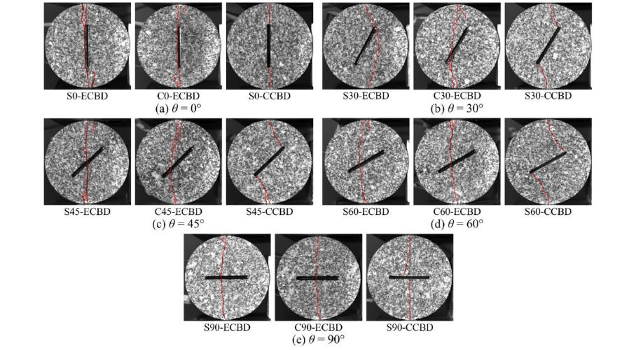
Fig.2 Comparison of macroscopic fracture modes of CCBD and ECBD specimens under different loading and inclination conditions. DIC high-definition imaging accurately reproduces crack initiation position, propagation path, penetration morphology and fracture characteristic differences.
4.2 Full-Field Tracking of High-Strain Zone Evolution by DIC
The maximum principal strain field calculated by the DIC system reveals the differentiated strain localization evolution law before and after grouting (Fig.3).
For CCBD specimens, high-strain zones appeared at prefabricated crack tips (0°, 30°, 45°, 60°) or on both sides of defects (90°) before peak load. The position and morphology of high-strain zones remained basically unchanged before and after peak load, with only strain intensity increasing. It indicates that the failure source zone of ungrouted specimens was determined by defect geometry at the early loading stage, and the subsequent loading process only induced local damage accumulation until crack penetration.
For ECBD specimens, high-strain zones were also distributed near defects before peak load. However, during the failure stage after peak load, high-strain zones migrated spatially. At 30°, 45° and 60°, high-strain zones transferred from crack tips to the strip zone along the loading axis at the specimen center. It demonstrates that the epoxy resin grouting body possesses sufficient strength, shares partial external load during loading, and effectively inhibits the initiation of early tensile cracks at defect tips.
The full-field observation of the DIC system provides direct visualized evidence for such reinforcement mechanism.
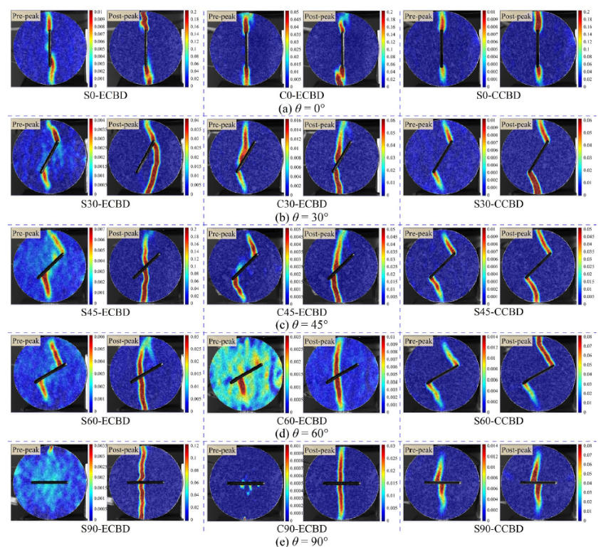
Fig.3 Full-field strain nephograms of granite specimens before and after peak load at different inclination angles calculated by DIC. It characterizes the initiation position, migration law and strain localization features of high-strain zones, and quantitatively compares the strain field distribution difference before and after grouting.
4.3 Quantification of Grouting Effect Based on Principal Strain Vector Field
The principal strain vector field extracted by the DIC system further quantifies the deformation inhibition effect of epoxy resin grouting (Fig.4).
At 0°, the principal strain vector direction of CCBD specimens was perpendicular to the loading direction, consistent with the theoretical splitting stress state, and the principal strain amplitude increased significantly at crack tips. The principal strain vector length of ECBD specimens before cracking was obviously smaller than that of CCBD, indicating that grouting effectively constrained local deformation near defects and reduced strain concentration.
At 45°, the principal strain direction of CCBD specimens deflected, presenting a composite deformation feature dominated by tension accompanied by local shear slip, which was consistent with the increase of shear crack proportion in AE analysis. After cracking, the principal strain vector field of ECBD specimens was similar to that of intact granite specimens; the vector direction converged to the unified orientation along the theoretical tensile direction, and the overall deformation coordination was greatly improved.
The principal strain vector characterization capability of DIC can distinguish the development mechanism of tensile and shear cracks from a mechanical perspective, and explain the internal mechanism of increased shear slip proportion and inhibited tensile cracking at 30°. Quantitative data show that the maximum principal strain of ECBD specimens is 30%–45% lower than that of CCBD under the same load level.
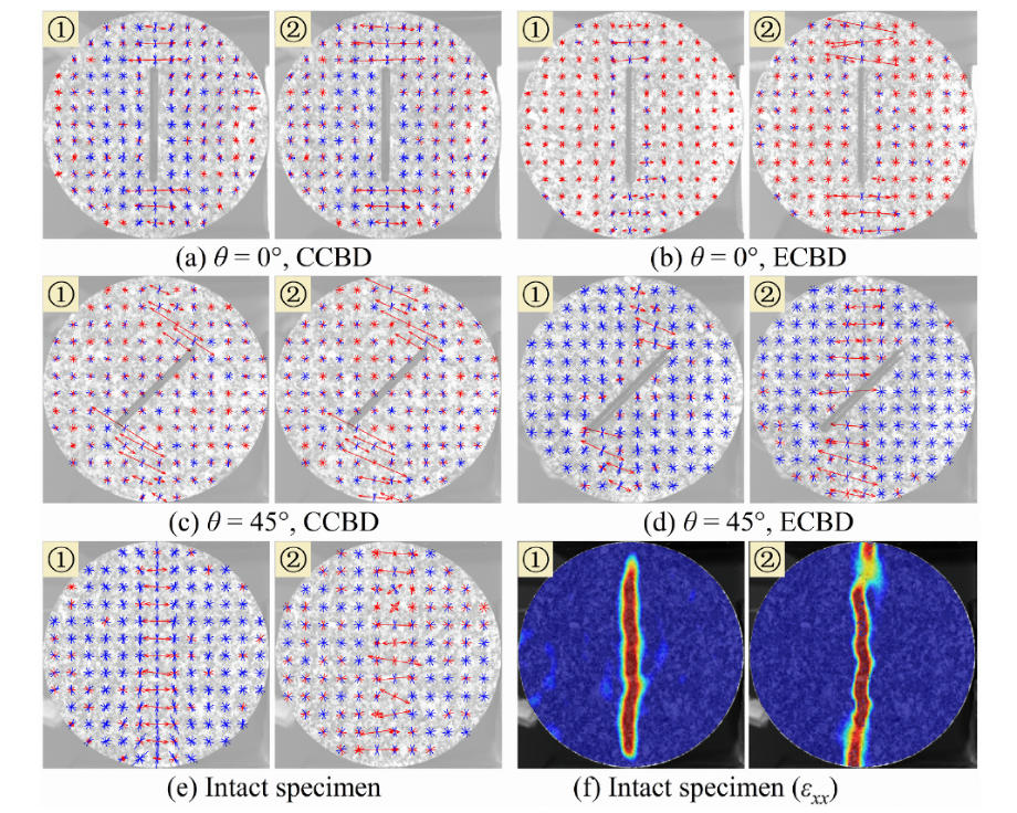
Fig.4 Principal strain vector field of granite specimens before and after cracking solved by DIC. It reveals the dominant mechanism of tensile-shear deformation at different inclination angles and the regulation effect of epoxy resin grouting on rock mass deformation evolution through the direction and amplitude of principal tensile and compressive strain vectors.
Taking DIC technology as the core observation method, this study systematically compared the fracture behavior of fractured granite with prefabricated central cracks before and after epoxy resin grouting under different inclination angles and static/dynamic loading conditions. The main conclusions are as follows:
I. The full-field multi-dimensional characterization capability of the DIC system is the core technical support for the research on grouting fracture mechanism of fractured rock masses. With the advantages of non-contact, full-field coverage and high temporal-spatial resolution optical monitoring, DIC can accurately capture crack initiation and propagation path, full-field strain temporal-spatial evolution and high-strain zone migration. It serves as a core experimental device for quantitative evaluation of grouting reinforcement effect and fracture mechanism research of fractured rock masses in slope and tunnel engineering.
II. Quantitative strain analysis shows that epoxy resin grouting can significantly improve the bearing performance of fractured granite, weaken stress concentration at crack tips, restrain the development of large-scale tensile cracks, and make the fracture mode and deformation behavior of grouted rock masses close to intact granite.
III. Crack inclination angle significantly regulates rock mass microfracture and strain evolution characteristics. The inclination angle of 30° is more prone to induce shear microcracks, and the DIC principal strain vector field can effectively distinguish the composite tensile-shear deformation mechanism.
This study established a DIC-AE joint monitoring evaluation method for fracture behavior of grouted fractured granite. Relying on the full-field deformation characterization advantages of DIC, a multi-scale evaluation system covering macroscopic fracture morphology, full-field strain distribution and mesoscopic principal strain vector evolution was formed. It provides solid experimental theoretical and technical support for risk assessment, stability evaluation and reinforcement scheme optimization of slope reinforcement and tunnel surrounding rock grouting engineering.
FAQ 1: What is the core advantage of Revealer DIC system in rock mechanics testing?
Revealer DIC system adopts non-contact optical measurement, which can realize full-field strain and displacement acquisition without pasting strain gauges. It can capture strain localization, crack tip deformation and high-strain zone migration that traditional point measurement cannot obtain, and is highly suitable for Brazilian splitting, uniaxial compression and fracture toughness testing of rock materials.
FAQ 2: Why choose Brazilian splitting test combined with DIC for grouted granite research?
Brazilian splitting test is the standard method to test rock tensile fracture characteristics. Combined with Revealer DIC, it can synchronously obtain macroscopic crack morphology and mesoscopic full-field strain evolution, realize multi-scale characterization of grouting reinforcement mechanism, and better reflect the actual stress state of rock mass in slope and tunnel engineering.
FAQ 3: What working parameters of Revealer GR220 DIC camera are adopted in this experiment?
The Revealer GR220 high-speed camera supports 1920×1080 resolution with a maximum frame rate of 2000 fps. The experimental configuration adopted 1000 fps frame rate, matched with synchronous trigger with mechanical loading and AE system, ensuring time-domain synchronization of multi-physical field data.
FAQ 4: What is the essential mechanism of epoxy resin grouting characterized by DIC?
DIC intuitively reveals that epoxy resin grouting weakens crack tip stress concentration, changes fracture from defect-controlled to load-controlled mode, increases shear microcrack proportion, reduces overall strain level by 30%–45%, and makes the deformation and fracture behavior of fractured rock close to intact rock.
FAQ 5: What engineering application scenarios can this DIC research achievement be applied to?
The research results can be directly applied to stability evaluation of slope grouting reinforcement, tunnel surrounding rock grouting modification, fractured rock mass disaster risk prediction, and provide standardized DIC testing paradigm for rock mechanics laboratory research and geotechnical engineering reinforcement effect evaluation.
 English
 Deutsch