Using two Revealer high-speed cameras and the binocular pose measurement module in REMA (Revealer Motion Analysis) software, calibration, stationary-state, and constant-velocity tests were performed on a cylindrical target, achieving a measured dynamic displacement error of less than 0.05 mm and a velocity error of less than 0.1 mm/s, while also validating continuous and stable output of pitch and yaw angles.
In dynamic measurement applications such as rigid-body motion, mechanism motion testing, and outdoor target tracking, users are primarily concerned with three questions: Can the target’s 3D displacement be reconstructed accurately? Can its velocity be measured stably during continuous motion? Can pitch and yaw variations be resolved reliably?
To evaluate these capabilities, Revealer engineers built a binocular measurement system using two high speed camera systems. A precision linear stage provided known displacement and velocity inputs, while the REMA binocular pose measurement module performed target detection, stereo triangulation, and pose estimation under repeatable experimental conditions.
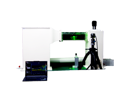
The measurement system consisted of Revealer high-speed cameras, a precision linear stage, a cylindrical-axis target, a calibration board, and REMA software.
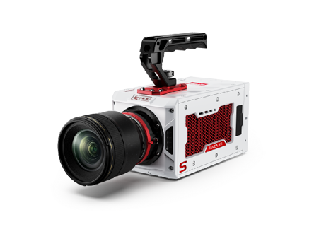
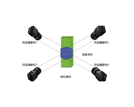
High-speed cameras: Two Revealer NEO25 high-speed cameras were used as the left and right imaging channels of the binocular measurement system. The two cameras synchronously recorded the moving cylindrical target, allowing target features captured at the same instant to be used for stereo geometric reconstruction.
Precision linear stage: The stage generated motion with a known direction, displacement, and velocity. The step displacement was 50 mm per step, and the velocity during the constant-speed phase was 20 mm/s. Motion parameters from the stage, together with laser distance measurements recorded during the experiment, were used as reference values for displacement and velocity comparison.
Cylindrical-axis target: A cylindrical target with a clearly defined centerline geometry was used for detection and tracking by REMA software.
REMA software: The software was used for binocular calibration, target definition, automatic detection and tracking, 3D reconstruction, kinematic calculation, and measurement result output. As a high speed camera software solution, it supports advanced image-based measurement workflows using Revealer imaging systems.
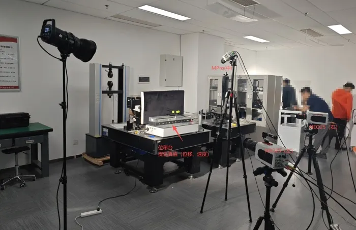
Figure 1. Experimental Setup for Binocular Pose Measurement Accuracy Validation Using REMA Software
The positions and orientations of the two high-speed cameras were first fixed. The stereo baseline and lens fields of view were adjusted so that the complete motion range of the cylindrical target remained within the overlapping field of view of both cameras.
After the system setup was completed, a fixed calibration board was used to calibrate the binocular vision system. The intrinsic and extrinsic parameters of the left and right cameras were calculated, and calibration quality was evaluated using the reprojection error and calibration-point spacing error.
A cylindrical-axis target was then created in REMA software. The software detected and tracked the target centerline and performed stereo triangulation based on the binocular calibration parameters to obtain the target’s 3D position. Pitch and yaw variations were subsequently calculated from the orientation of the reconstructed spatial axis.
The measurement workflow was:
Synchronized image acquisition → Target detection and tracking → Stereo triangulation → Pose and kinematic calculation → Data output
Two operating conditions were evaluated. In the first condition, the target remained completely stationary to assess the stability of displacement, velocity, and pose outputs. In the second condition, the linear stage moved at a constant velocity of 20 mm/s over a total travel distance of 100 mm, allowing the dynamic displacement and velocity measurement capabilities of the REMA binocular pose measurement module to be evaluated.
The binocular calibration produced a reprojection error of 0.075 pixel and a calibration-point spacing error of 0.029 mm.
The subpixel-level reprojection error indicates that the geometric calibration of the left and right Revealer high-speed cameras achieved good fitting quality under the present experimental conditions, providing a reliable geometric basis for subsequent 3D measurement.
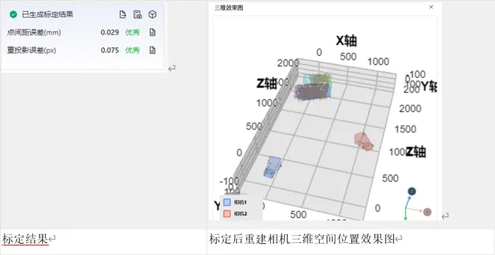
Figure 2. REMA Binocular Pose Measurement Calibration
When the target remained completely stationary, the theoretical displacement increment and velocity should both be zero.
After weighted averaging and smoothing, the displacement variation reported by the REMA binocular pose measurement module remained within 0.03 mm, the velocity variation remained within 0.1 mm/s, and the stationary pose-angle variation remained within 0.03°.
These results show that, in the absence of actual motion input, the 3D position, velocity, and pose outputs of the REMA binocular pose measurement module converge stably.
With the linear stage moving at 20 mm/s over a total displacement of 100 mm, REMA software continuously output the target’s 3D position curve.
The recorded dynamic displacement error was less than: 0.05 mm
The results indicate that, under the motion velocity, image scale, binocular baseline, and target-feature conditions used in this experiment, the target centerlines in the left and right images remained continuously matched, and no obvious accumulated drift was observed in the stereo triangulation results.
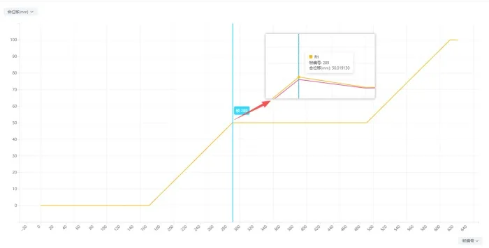
Figure 3. 3D displacement measurement curve from REMA software using two Revealer high-speed cameras during 20 mm per second linear motion
The linear stage moved at a constant velocity of 20 mm/s. The velocity curve output by REMA clearly captured the acceleration/start phase, constant-velocity phase, and stopping phase.
During the constant-velocity phase, the measured velocity followed the stage setting, with a recorded velocity error of less than: 0.1 mm/s
This result demonstrates that, at the tested motion velocity, the time-resolved image sequence acquired by the two high-speed cameras was sufficient for continuous position reconstruction. After temporal processing, the reconstructed position data could further be used to calculate target velocity.
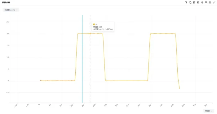
Figure 4. Velocity measurement curve from REMA binocular pose module compared with laser distance measurement reference during 20 mm per second motion
During the dynamic test, REMA software continuously output yaw-angle and pitch-angle curves.
Because the linear stage could not be perfectly leveled with respect to the measurement coordinate system, small pose variations occurred during motion. The measured results continuously reflected this trend, validating the ability of the REMA binocular pose measurement module to resolve changes in target orientation while maintaining continuous and stable pose-angle output.
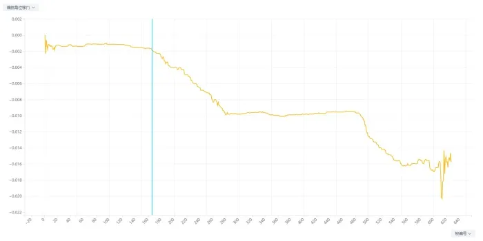
Figure 5. Yaw angle measurement curve from REMA software using binocular high-speed camera pose measurement
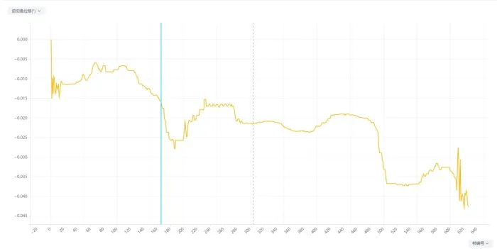
Figure 6. Pitch angle measurement curve from REMA binocular pose measurement using two Revealer high-speed cameras
This experiment used two high-speed cameras to construct a binocular vision measurement system. A precision linear stage drove a cylindrical target, and the binocular pose measurement module in REMA software was evaluated through calibration, stationary-state testing, and constant-velocity motion testing.
Within the tested operating conditions:
I. The binocular calibration achieved a reprojection error of 0.075 pixel and a calibration-point spacing error of 0.029 mm, providing a stable geometric calibration basis for subsequent 3D reconstruction.
II. Under stationary conditions, after weighted averaging and smoothing, the 3D displacement output fluctuation remained below 0.03 mm, the velocity output variation remained below 0.1 mm/s, and the pose-angle output variation remained below 0.03°, demonstrating good static measurement stability.
III. Under dynamic conditions, the recorded displacement error was below 0.05 mm and the velocity error was below 0.1 mm/s. REMA software maintained continuous binocular target tracking and completed continuous 3D position and velocity calculation.
IV. For pitch and yaw analysis, the experiment verified the ability of REMA software to continuously output pose angles and resolve small angular variations. A dedicated follow-up calibration using an independent high-precision rotary stage will be introduced to further validate the absolute angular accuracy of the REMA binocular pose measurement module.
 English
 Deutsch